What are some good practices in documenting system architecture and processes?
Contents
What are some good practices in documenting system architecture and processes?#
Contributor(s): Siti Nuruljannah Baharudin, AI Engineer
In machine learning projects, documentation should be treated like a growing entity that is maintained the way we maintain code. At the same time, we do not want to spend excessive effort documenting details that may rapidly change over the course of the project. In the systems and software engineering fields, modelling languages such as UML are used to document system architecture and processes. Although they will not be discussed here, the concepts from these modelling languages can be adopted to suit the documentation requirements of your project.
Use simple visuals#
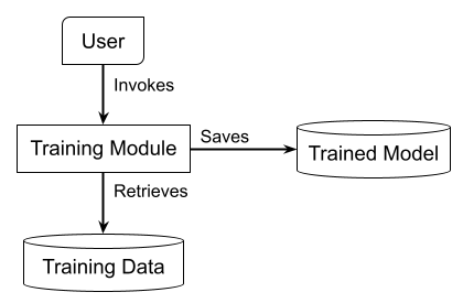
Box-and-arrow diagrams are a simple and easily maintainable visual method to document system architecture and processes. This example shows how a high-level process can be illustrated with a box-and-arrow diagram:

Consistency in notation#
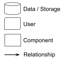
Choose a shape to denote each element and a line to denote each relationship or flow, and stick to these choices for all diagrams used in your documentation. This basic set of notations is a good place to start.

One diagram per process#
Illustrate only one process per diagram. If there is a need to show lower-level detail of a process, create a separate diagram for that. I would recommend using the C4 model as a guide. It defines four levels of diagrams - Context, Container, Component and Code - based on a hierarchy of abstractions.
Consider your audience#
Within the development team, it may be worth the while to create up to level 3 (Component) diagrams. However, such diagrams may not be useful to non-technical people outside the development team. Furthermore, as they contain implementation details, these diagrams likely get outdated quickly.
In documentation delivered to end-users, Context diagrams would typically suffice for the general audience, to whom the solution is a black box. On the other hand, if the users are technical people and require understanding the inner workings of the system, including the lower-level diagrams would be a good idea. It is recommended that you automate the generation of Component and Code diagrams to minimise the effort spent on maintaining them.
Design considerations#
Colour#
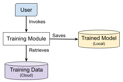
Besides shapes, colours may also be used to visually differentiate between element types. For instance, in the diagram below, purple is used to denote a remote storage location while yellow is used to denote a local storage location.

It is best that you refrain from relying only on colours to relay information in your diagram as there could be readers who have difficulty distinguishing colours. The use of colours should serve to improve understanding of the diagram and increase its visual appeal for the average reader.
Labels#
As seen in the earlier examples, every element and relationship in your diagram should be labelled. A label should be specific yet concise, in a legible font.
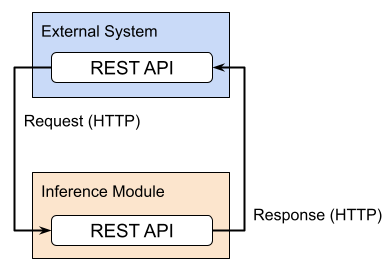
In a system architecture diagram, the relationships between elements should have the protocol or technology explicitly labelled, as seen in the example below.

Reference(s):
Bhatti et al. (2021) Docs for Developers: An Engineer’s Field Guide to Technical Writing.
 Horizontal Logo CMYK Full Colour.png)